ASU Solar Car Rear Suspension
My senior mechanical design project catered to Arizona State University's solar car racing team
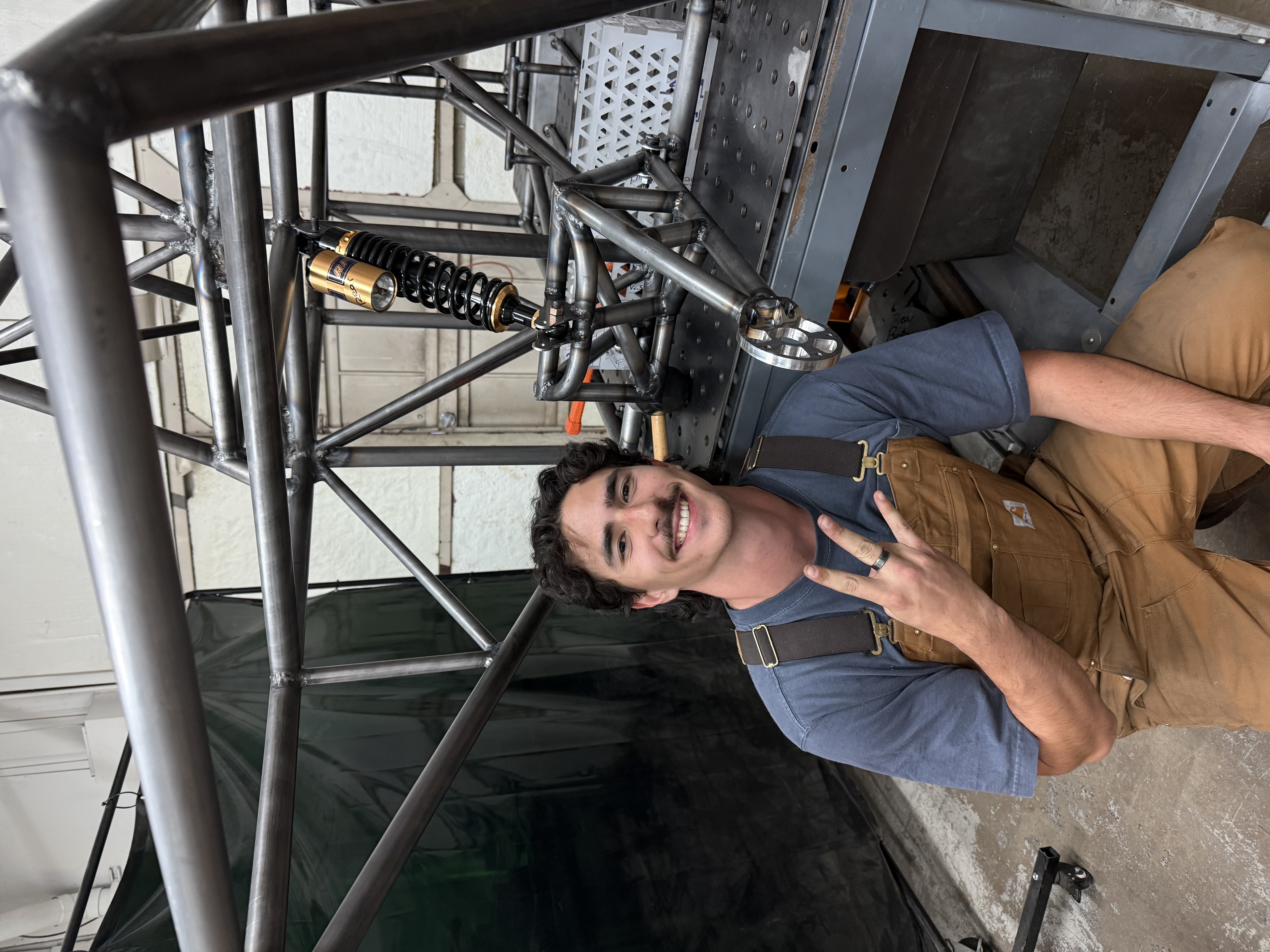
Me with the trailing arm!
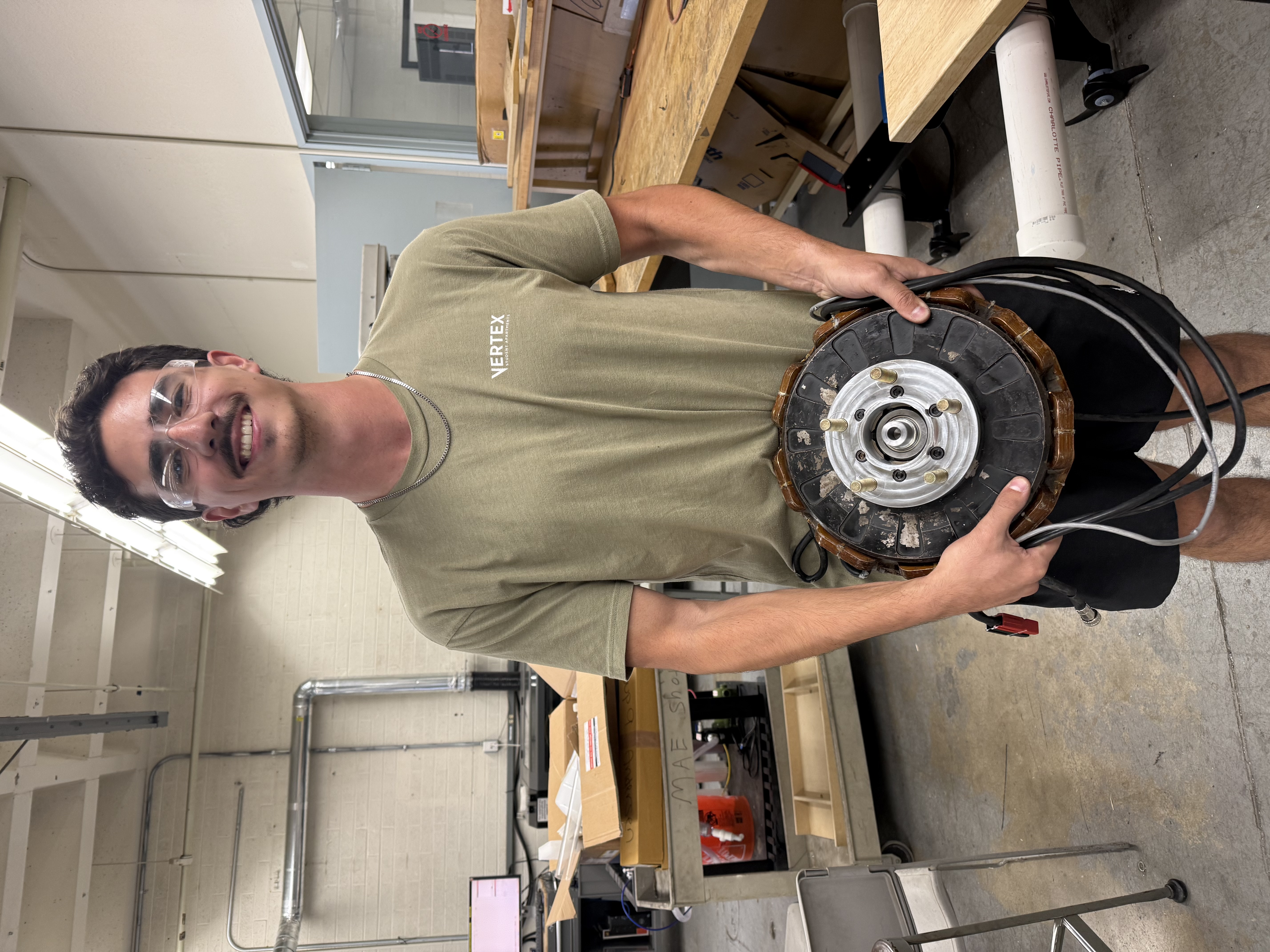
Me holding our electric motor and wheel adapter (so heavy!)
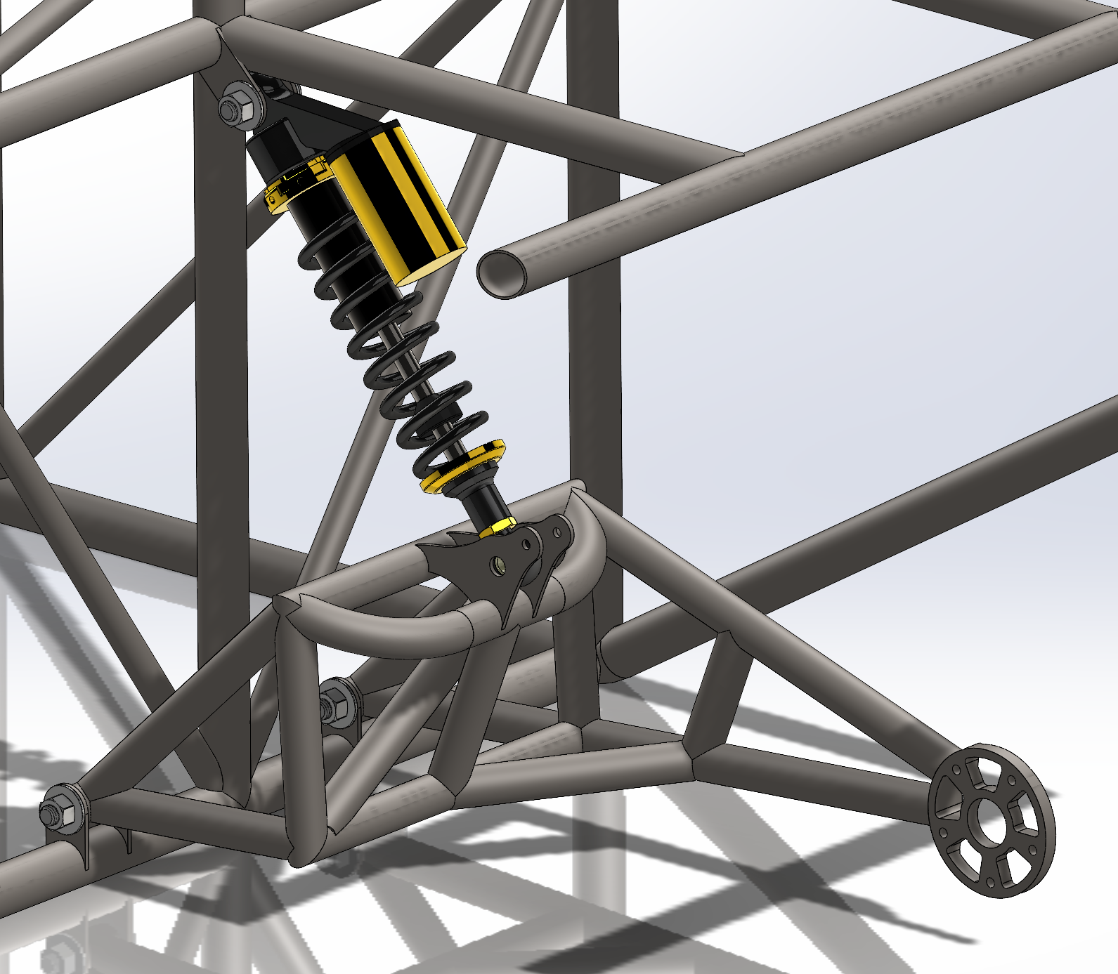
SolidWorks assembly CAD model I created of the rear suspension
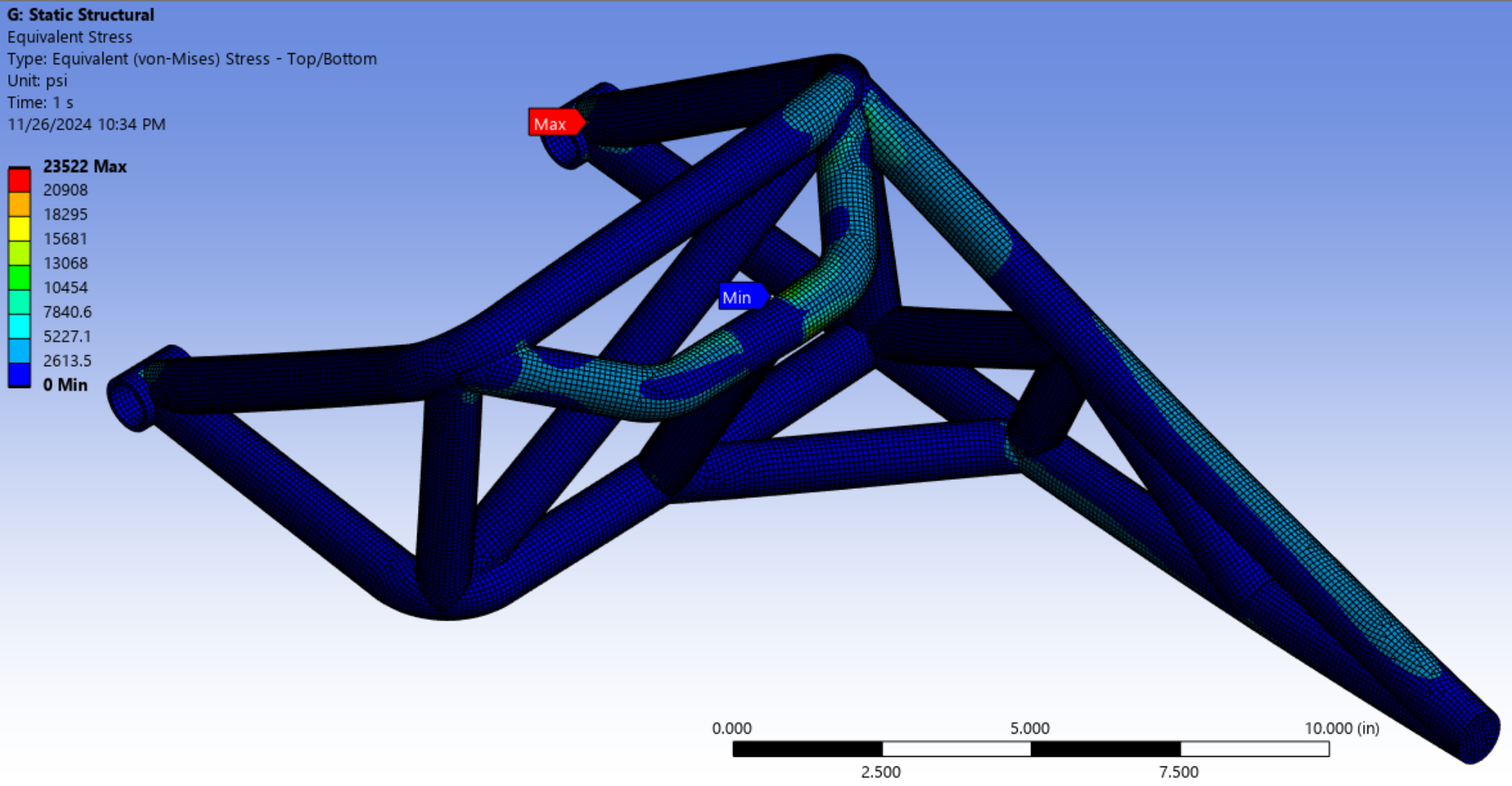
Ansys Structural simulation of the maximum stress the trailing arm will experience
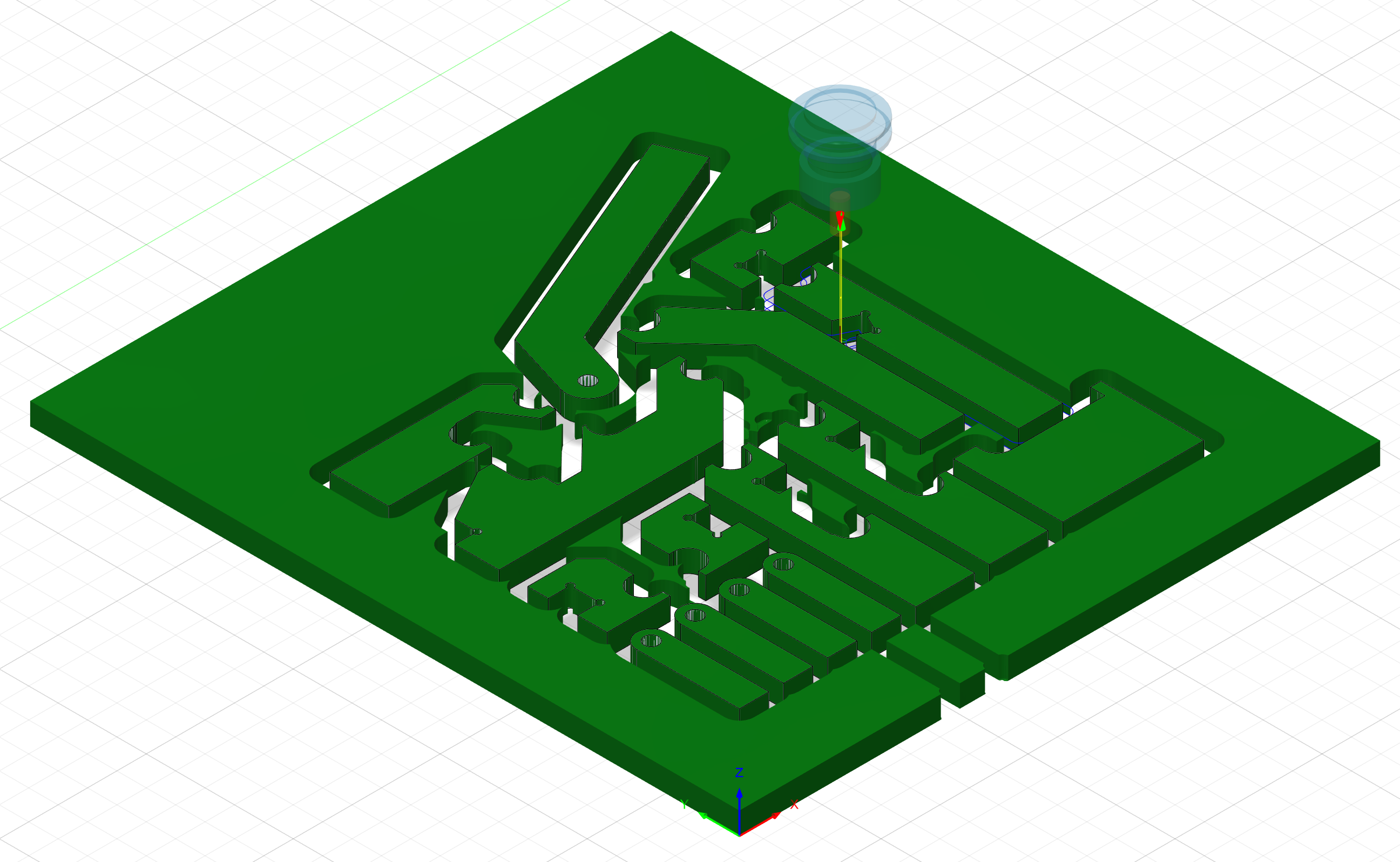
Fusion360 CAM model I created to create the weld fixtures
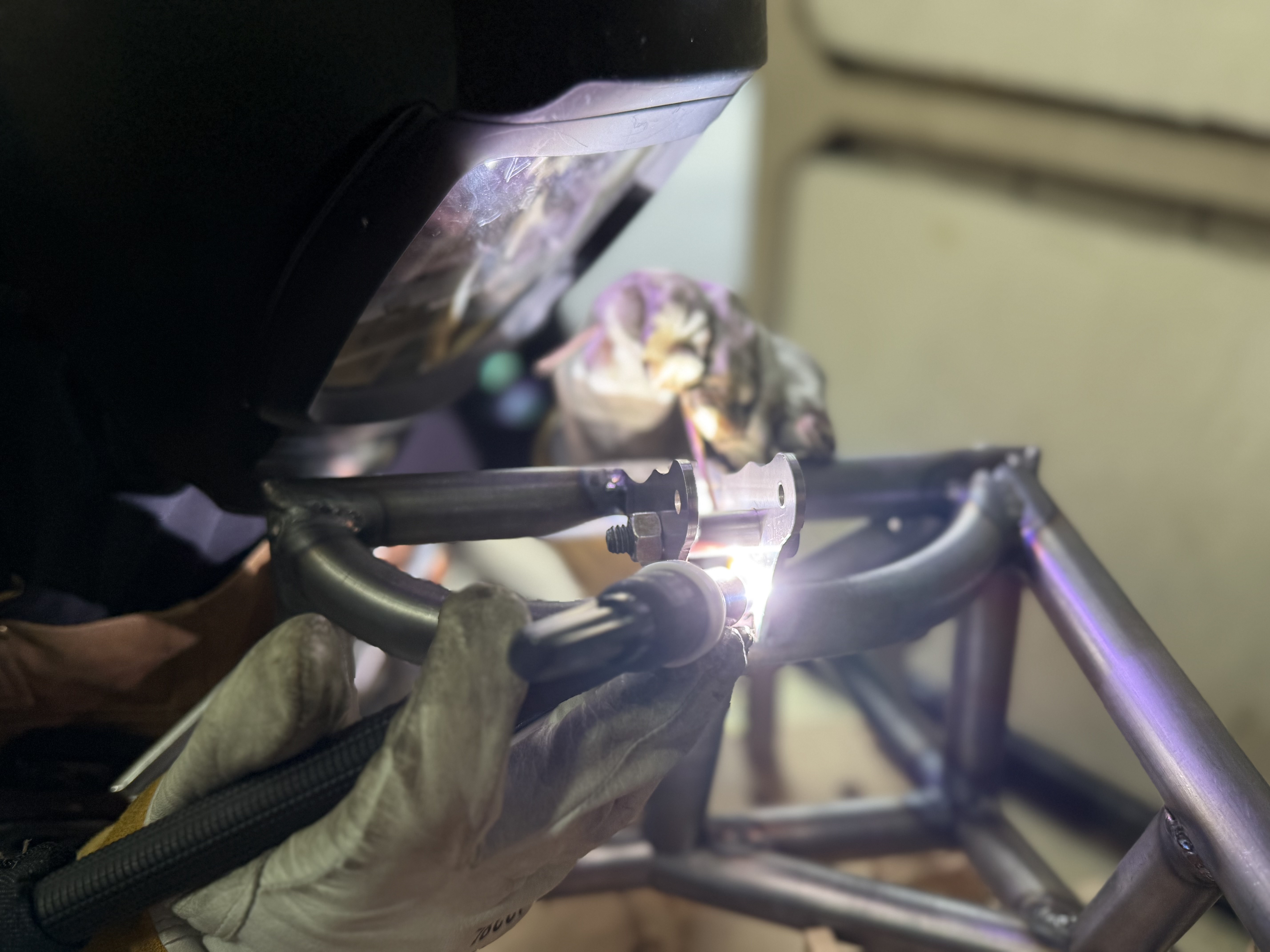
TIG welding the trailing arm
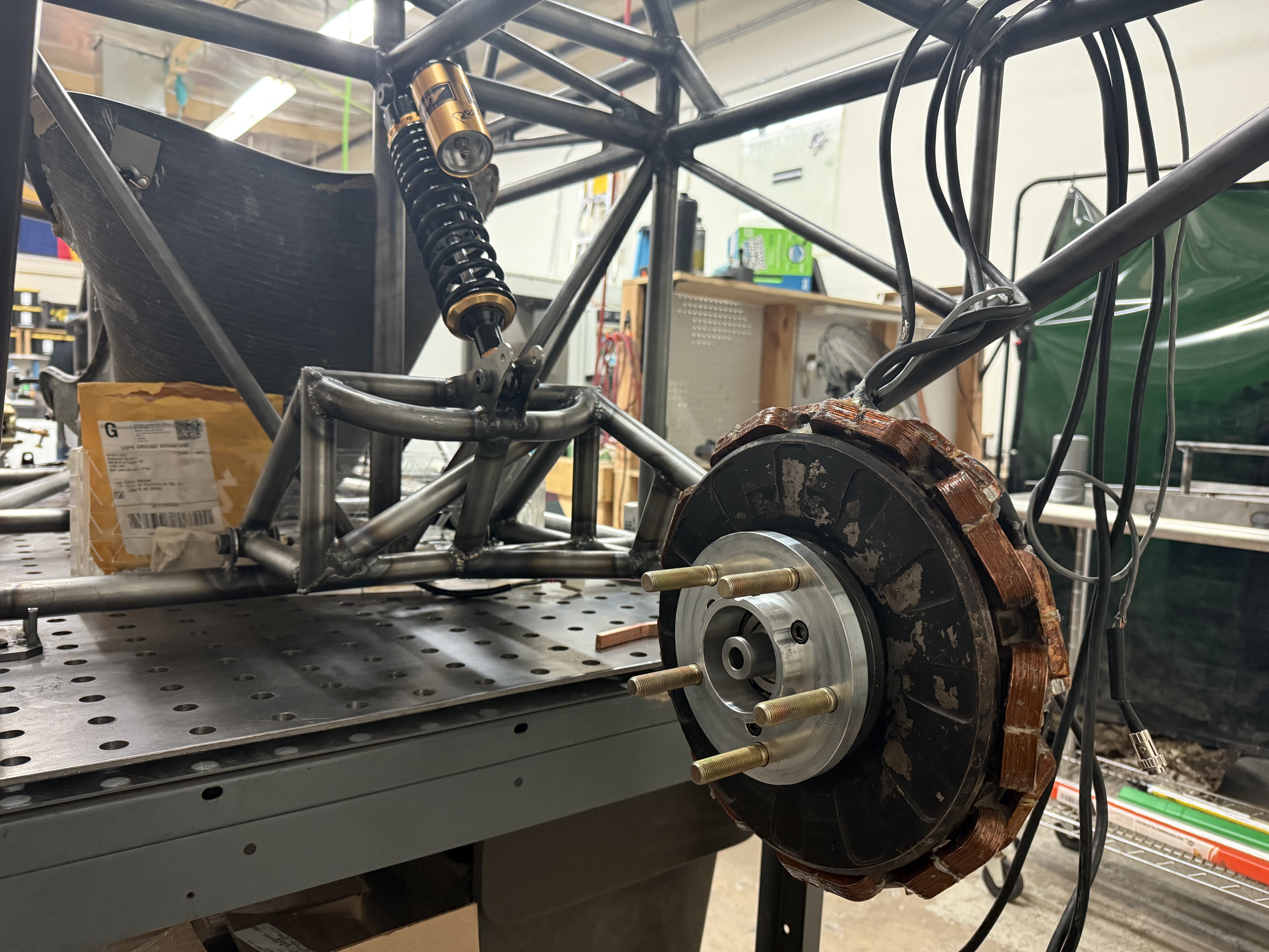
Trailing arm and motor mounted to the chassis
Overview
I proposed this project during my fall semester in my senior year of my bachelor's degree. Going into the year, as the mechanical lead of university's solar car team, I knew that the car still desperately needed to start design and fabrication of our rear suspension. I decided to enlist the help of some fellow classmates to help me with the development of this system. Because of my familiarity with the solar car and the existing challenges of implementing the design, I led the project and was heavily involved in the CAD modeling, finite element analysis, and fabrication of the system. It was important for this system to comply with American Solar Challenge regulations, as well as criteria that were set in place by the solar car team. The selected design was a trailing arm with a raised shock absorber mounting point to close distance between the trailing arm and chassis whilst also utilizing the most stiff points of the chassis. Welded together with chromoly steel tubing and machined components, the suspension complied with the competition loading conditions, was compatible with existing solar car systems, and also was optimized for strength, weight, and manufacturability.
Key Features
- Withstands 2G bump, 1G turn, and 1G brake loading conditions simultaneously with a FOS of 1.5
- Compatible with team chassis and electric in-hub motor
- Allows for optimal wheel travel while remaining stiff enough to avoid bottoming out
- Has mounting space for future wheelwell cover
Process
- Understood the problem statement, requirements, and constraints
- Benchmarked with existing solutions to base the custom design
- Brainstormed different configurations and narrowed them down using a decision matrix
- Conducted static hand calculations on final designs to inform FEA boundary conditions
- Created a preliminary CAD model in SolidWorks to iterate and optimize in FEA
- Validated model in Ansys and adjusted for manufacturability
- Constructed weld fixtures in CAD and fabricated using a CNC router
- Welded trailing arm components together within weld fixture
- Assembled and installed system on solar car chassis
- Tested performance in both static and dynamic environments
Tools
Skills
Outcomes and Results
By installing a working raised trailing arm suspension onto the solar car, I successfully created a mechanical system that exemplified my ability to:
- Formulate design objectives, constraints, functions, and metrics
- Create and evaluate design concept alternatives
- Manage a design project scope, schedule, and budget
- Construct, test, and deliver a proof-of-concept prototype
In my master's year, I plan to continue dynamic testing as the aeroshell of the car gets built and possibly incorporate a fatigue test analysis to see if the design has infinite life.
Reflection
Reflecting on this project, I am very proud of the work that was accomplished. This was one of the first projects I completed that I was able to execute the entire mechanical design process from start to finish, building off the skills and knowledge I had gained throughout my degree. Even better, the project was related to something I was extremely passionate about, making it easy to give 110% of my effort. I realized what I was truly capable of as an incoming mechanical engineer to the industry - to be able to provide working solutions, especially in the automotive industry. I hope to translate the skills demonstrated in this project to a career in building an optimistic future for human transportation.