Front Suspension
Custom double wishbone suspension system emphasizing a small form factor
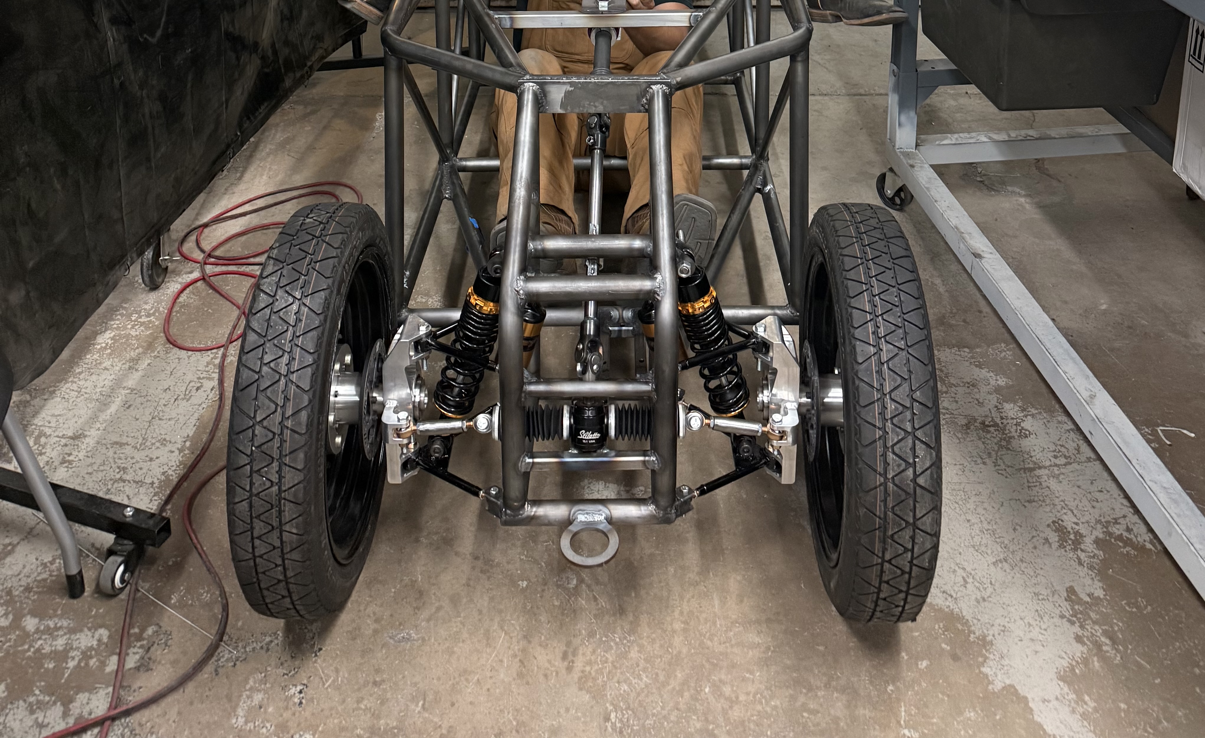
The double wishbone suspension in all of its glory
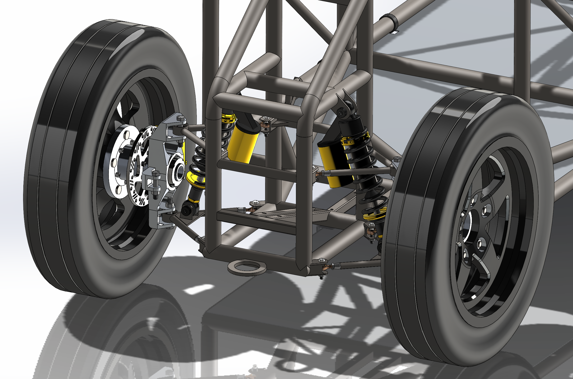
SolidWorks assembly CAD model I created of the front suspension
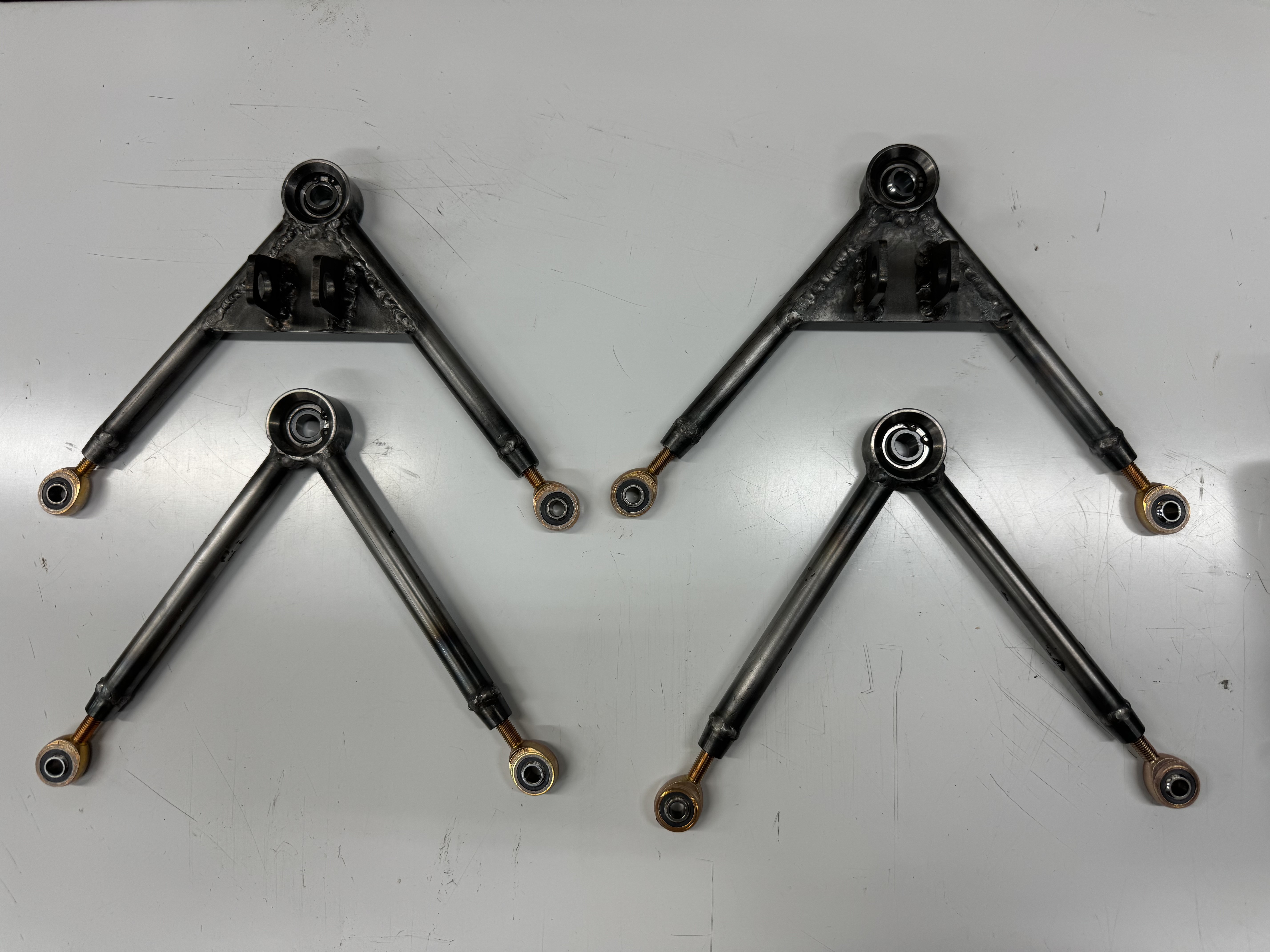
Simple welded chromoly steel control arms assembled with hardware
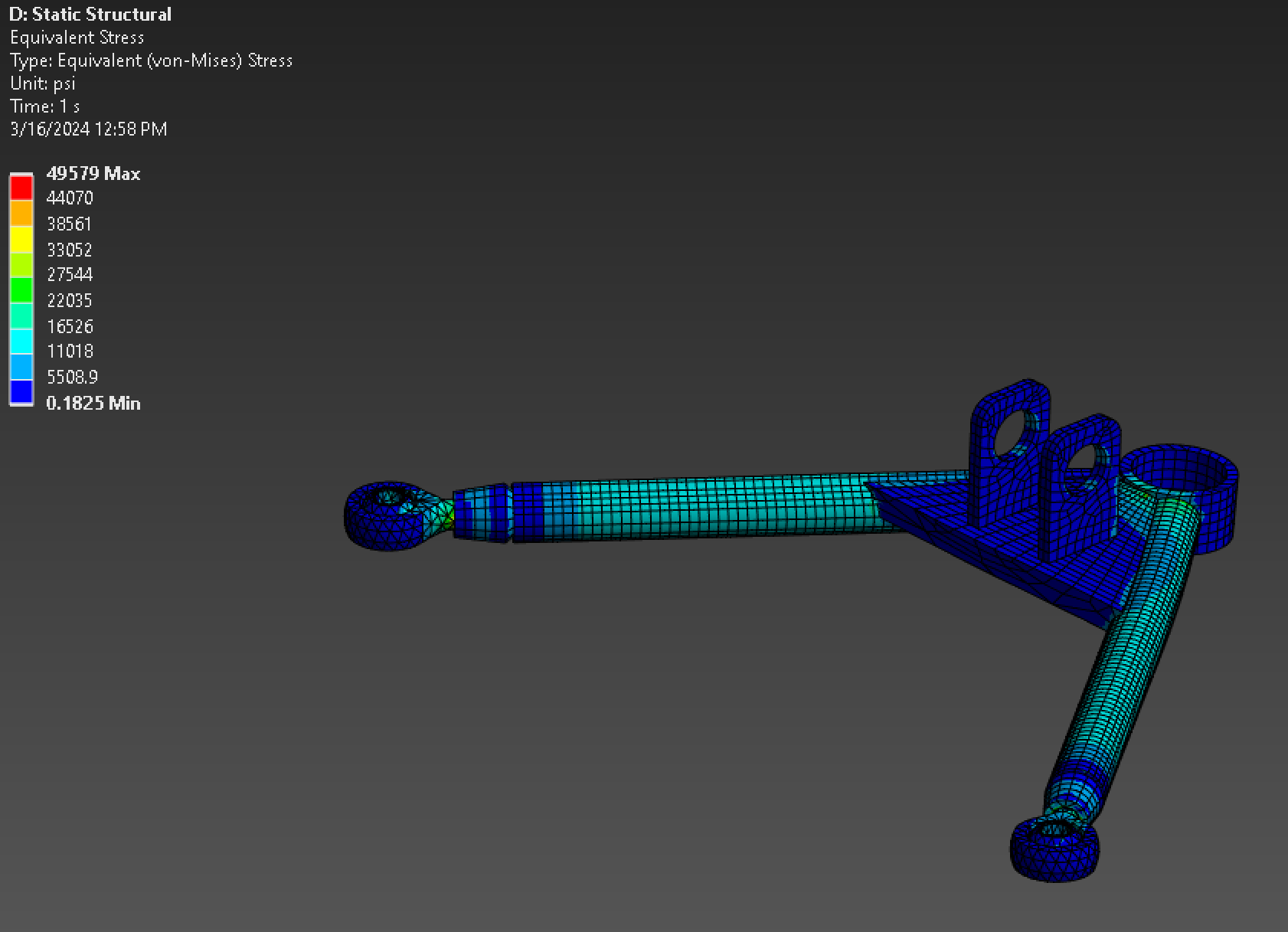
Ansys Structural simulation of the maximum stress the control arm will experience
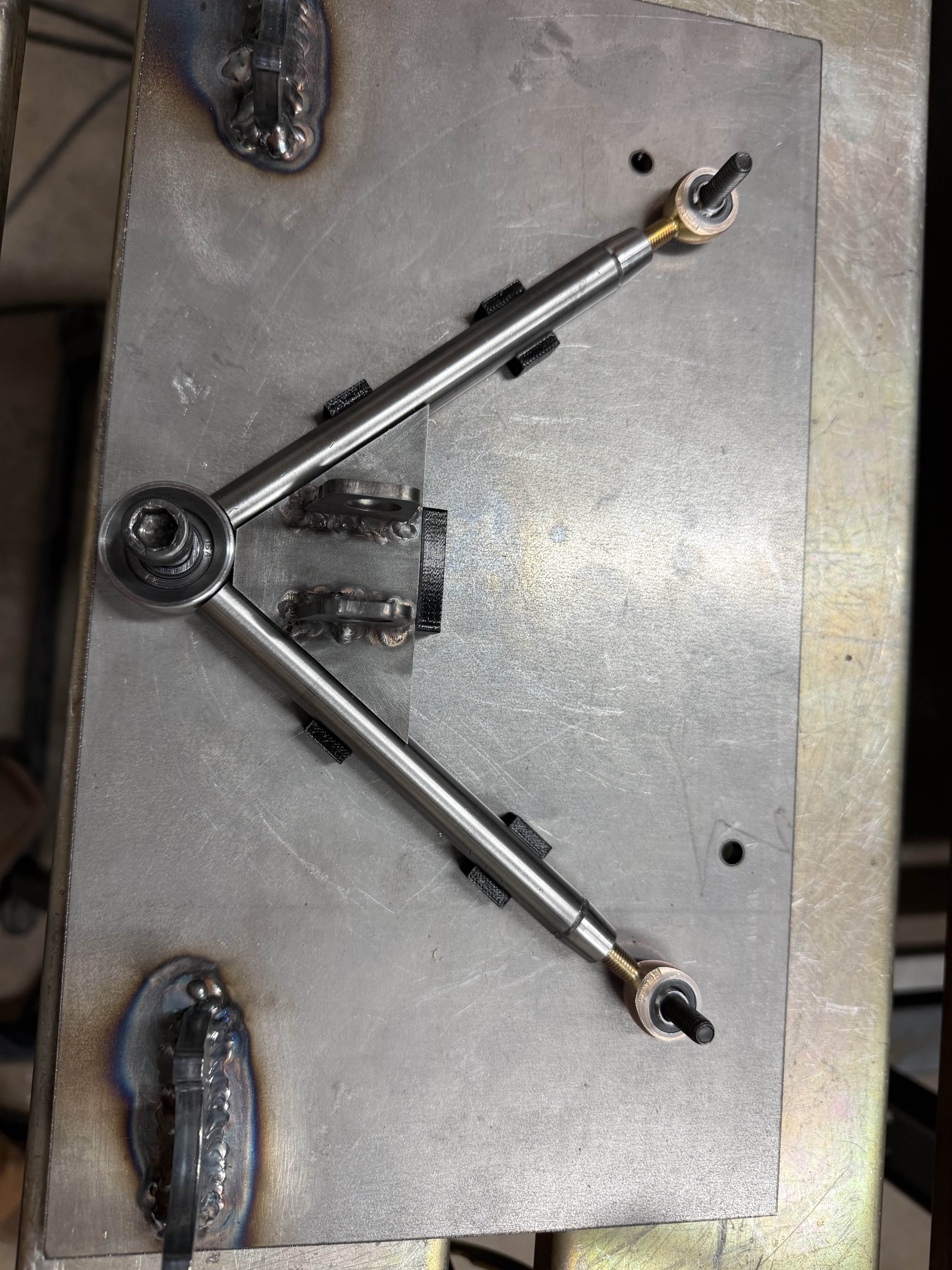
Control arm in the fixture plate designed to locate important mounting holes
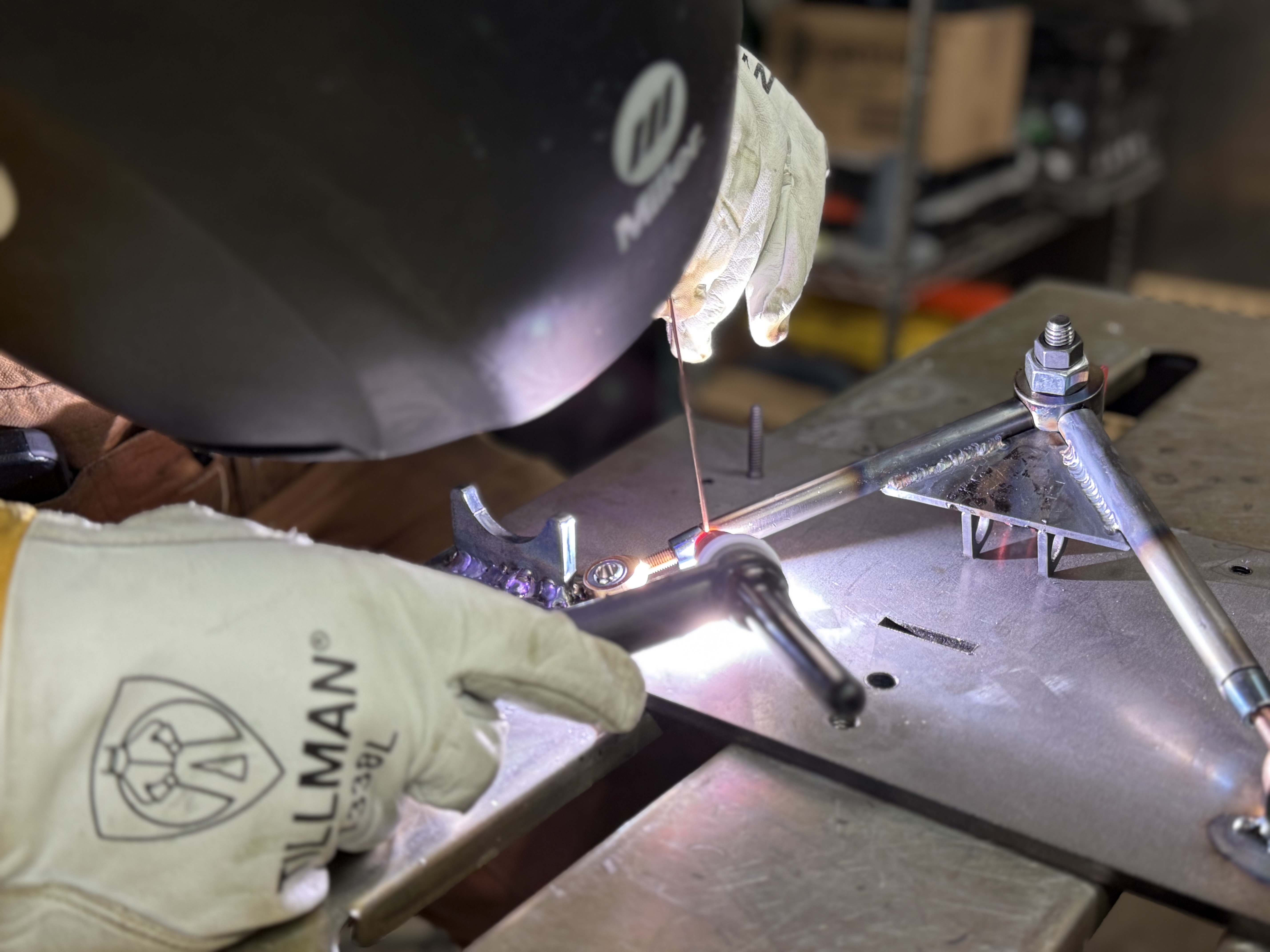
TIG welding the control arms
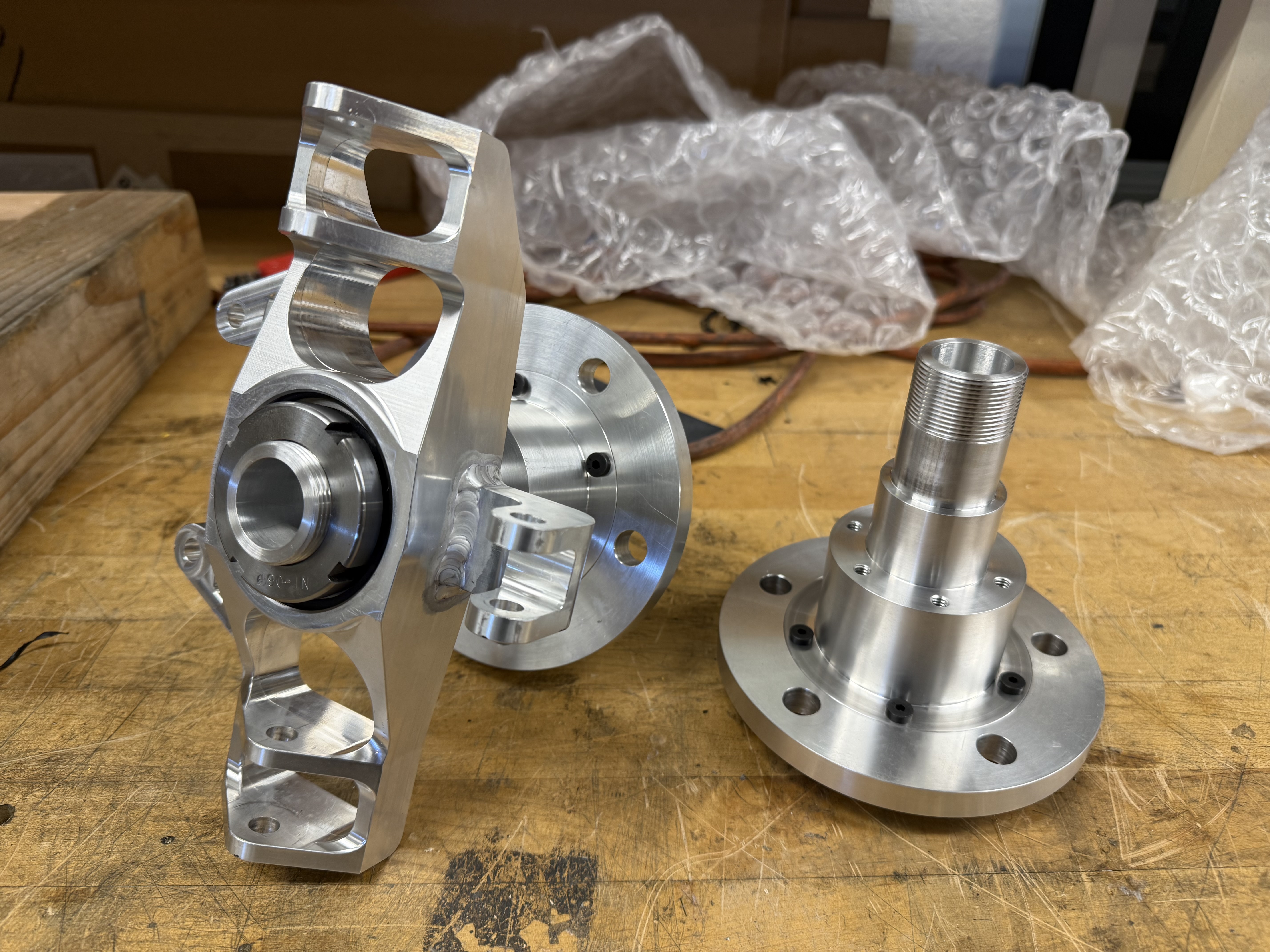
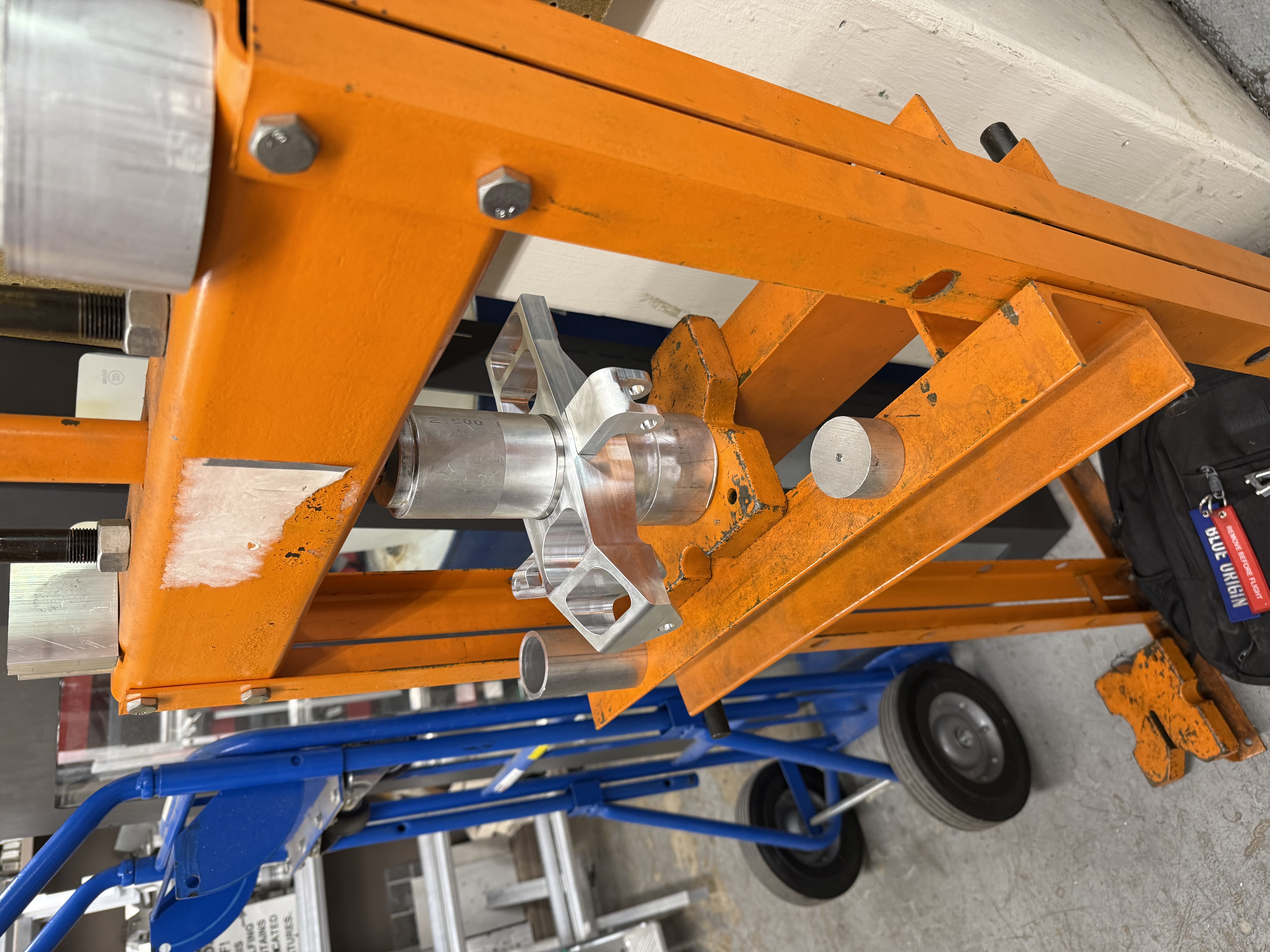
Freshly machined upright, spindle, and wheel hub, interfacing as intended
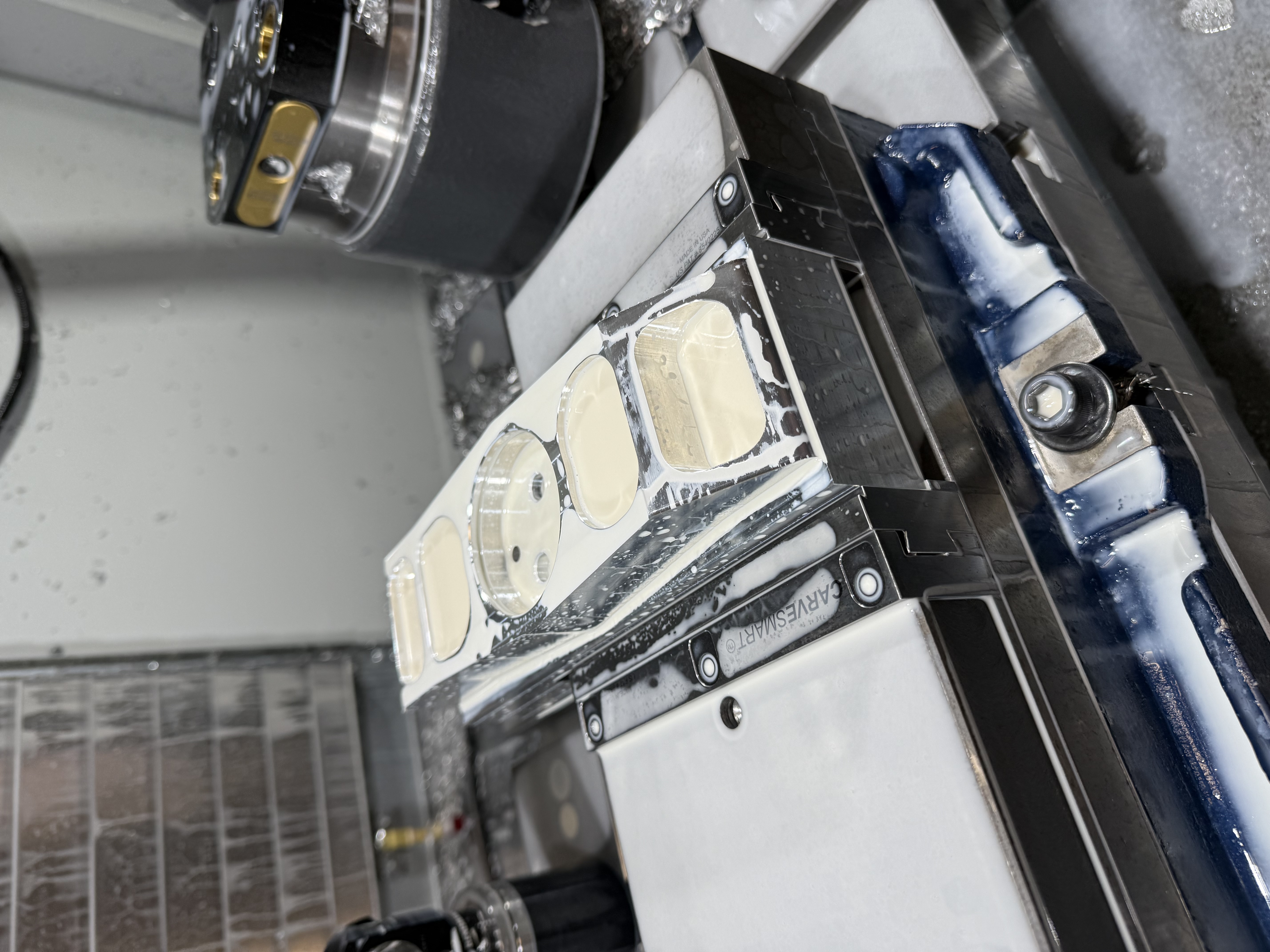
Upright in the CNC mill fixture, mid-operation
Using an arbor press to press-fit bearings into the uprights
Overview
While chassis fabrication was happening, I designed our front suspension simultaneously to ensure compatibility. One of the bigger goals with this car was to maintain a thin profile, and keep our track width low - while still being mindful of the possibility of stability loss. A double wishbone configuration was chosen for its overall mechanical simplicity and ease of manufacturing, while still achieving the objective. It is comprised of an array of major components:
- Uprights
- Wheel Hubs
- Spindles
- Control Arms
- Coil Over Shocks
The uprights were machined out of 6061-T6 aluminum, serving as the component where the spindle, control arms, brake caliper, and steering linkage all interface. Similarly, the wheel hubs and spindles machined and turned respectively out of 6061. These components directly mate with each other with bolts and weld reinforcement. The control arms were assembled out of mixture of welded 4130 chromoly steel tubing, weldable rod ends, and spherical bearings. This gave the control arms full adjustability, sufficient travel, and strength for the application. Lastly, the coil over shocks were purchased off the shelf as a full assembly with a spring stiffness and size that fit our need. This system gave me the opportunity to exercise my DFM skills, requiring extensive communication with the ASU machinists to make sure the design components were feasibly and optimally manufacturable.
Process
- Iterated in SolidWorks with a 3D sketch modeling the dynamic travel of the shock and linkage
- Modeled uprights and control arm assemblies, considering COTS hardware that each part needed to interface with
- Validated individual part response to shock loads in Ansys
- Communicated DFM strategy with ASU machine shop to machine/turn uprights, wheel hubs, and spindles
- Designed weld fixtures for control arms to locate rod ends and spherical bearings at true position during welding
- Assembled system with proper hardware
Tools
Skills
Outcomes and Results
The final assembly of the front suspension double wishbone went surprisingly well. The inclusion of adjustable threaded rod ends made for a very easy assembly process. When everything was attached there was no sign of interference during turning, speed bumps, and other dynamic tests. Additionally, there were no signs of plastic deformation or yielding in any part, which reinforced the Ansys results. Having had much experience with steel and welding it after the chassis the mechanical team made a much cleaner result for the control arms, which I would say are some of the most aesthetically pleasing components on the solar car. One part of the assembly process that remains challenging however, is placing the shocks inside their mounting points. I plan to design a custom shock compressor - catered to our spring size, to hopefully make that process go more smoothly. Overall, the team and I look to continue testing the front suspension under full car weight later in the 2025 school year.
Reflection
This system really strengthened my understanding of the importance of designing parts that are possible to make with machines that are widely available in engineering. Communicating with machinists has taught me tons about the easiest and most cost-effective ways to achieve certain features in machined parts. Considering how valuable doing this is in industry, I consider this experience invaluable. Some decisions in the suspension design process were made without the input of a machinist, and definitely made some aspects of the system more difficult to make. Given the opportunity to do it again, I would have made the hub and spindle in one machined part vs two, as the cost difference does not end up being worth the added machining time. Additionally, I was made aware of the importance of knowing the standard hardware on the shelf and making sure custom designed parts interface with what is accessible off the shelf. It would be undesirable to design a part that uses a very niche bolt or bearing size when it could be avoided, and then have to pay a premium for a rarer COTS part. In contrast to the chassis, I had full design ownership of the hardware in this system and it was a real treat to see my work come to life.